![]()
Murata muRata winding inductance original authentic assured purchase
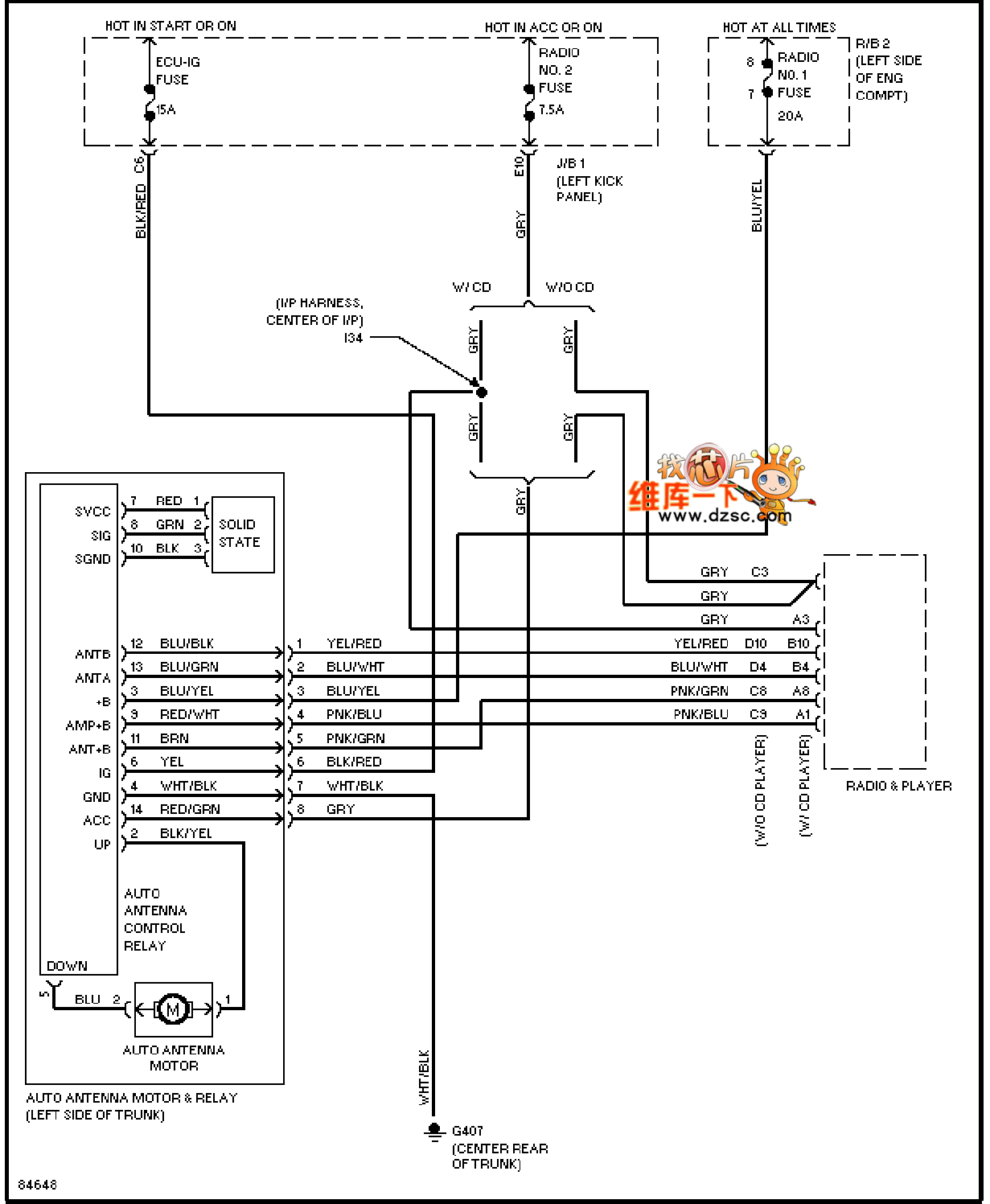
The 96-year Lexus SC400 electric antenna circuit diagram is as follows:

Welcome to reprint, information source Huaqiang Electronic Network ()
1. Overview
The automotive electric antenna circuit diagram usually describes the antenna system's electrical connections, control logic, and interfaces with other vehicle systems. In the 1996 Lexus SC400 electric antenna circuit diagram, we may see the following key parts:
2. Power and Ground
Power: The circuit diagram will show how the electric antenna gets power from the vehicle's power system (such as the battery). It may include protection components such as fuses and relays.
Ground: Show the ground connections of various parts in the circuit diagram to ensure the stability and safety of the circuit.
3. Control Circuit
Control Logic: Show the control logic of the electric antenna, such as receiving control signals through the body control module (BCM) or other control units.
Switch Signal: The circuit diagram will include the switch signal used to control the antenna's lifting and lowering.
Sensor Signal (if applicable): If the electric antenna has an automatic lifting function, it may also include sensor signals, such as sensors for detecting the antenna's position.
4. Signal Transmission
Antenna Signal: If the electric antenna has a signal receiving or transmitting function (such as for vehicle communication or navigation), the circuit diagram will show the transmission path of these signals.
Interface: Show the connection interface between the electric antenna and the radio, navigation system, etc.
5. Wiring Harness and Connectors
Wiring Harness Types: The circuit diagram will show in detail the types of wiring harnesses and cables used in the electric antenna system.
Connectors: Include codes for connectors and components to facilitate correct identification and connection in actual operation.
6. Graphic Symbols and Codes
Graphic Symbols: Specific graphic symbols will be used in the circuit diagram to represent various electrical components and connection relationships.
Codes: The codes for connectors and components will be used to identify their types and locations.


