Privacy statement: Your privacy is very important to Us. Our company promises not to disclose your personal information to any external company with out your explicit permission.
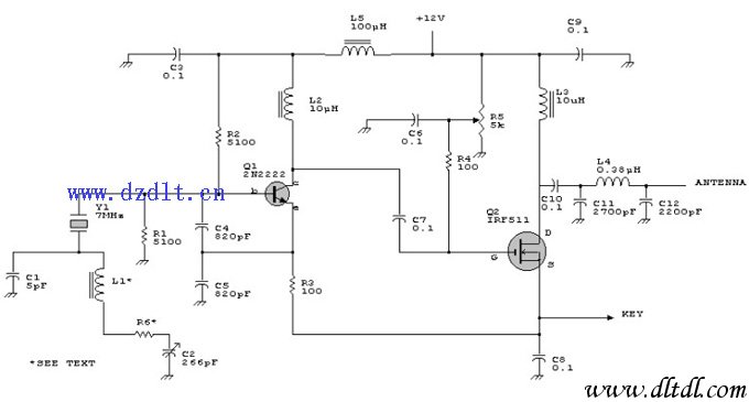
 Antenna circuit schematic
1. Basic components
An antenna circuit usually includes the following basic components:
Antenna element: This is the core part of the circuit, responsible for converting electromagnetic waves into current (reception) or converting current into electromagnetic waves (transmission).
Feed network: A network used to connect the antenna to the transmitting/receiving device (such as a radio transceiver). It may include an impedance matching network to ensure optimal power transfer between the antenna and the device.
Protection components: Such as fuses, relays, etc., used to protect the circuit from damage such as overcurrent and overvoltage.
2. Simplified circuit diagram description
The following is a simplified antenna circuit diagram description:
Antenna element: Represented as a symbol, which may be a simple straight line (representing a dipole antenna) or a more complex shape (representing a specific type of antenna, such as a helical antenna, microstrip antenna, etc.).
Feed network: A line leads from one end of the antenna element to the transmitting/receiving device. On this line, there may be one or more impedance matching elements (such as inductors, capacitors) used to adjust the impedance of the circuit to achieve the best match with the device.
Protection components: There may be a fuse or relay at the front or back end of the feed network to cut off the circuit when an abnormal situation such as overcurrent or overvoltage occurs in the circuit.
3. Combined with the information of the reference article
Impedance matching: Reference article 4 mentions the importance of impedance matching, especially in RFID applications. The impedance matching network in the antenna circuit can ensure the best power transfer between the antenna and the transceiver. This is usually achieved by using components such as inductors and capacitors.
Antenna type: Reference article 3 mentions different types of mobile phone antennas, such as IFA, Monopole, Loop, etc. Although these are specific types for mobile phone antennas, they also reflect the diversity of antenna design. In the actual antenna circuit diagram, the shape and size of the antenna element will be determined according to its application and design goals.
Safety protection: Reference article 2 mentions the antenna circuit that suppresses intermodulation products by providing different signal paths and attenuation values. Although this is different from direct safety protection, it shows the importance of considering various potential problems in antenna circuit design. Safety protection components such as fuses play a key role in preventing circuit damage.
Wifi Antenna, Router Antenna, Patch Antenna
June 28, 2024
Wyślij je do tym dostawcy
June 28, 2024

Privacy statement: Your privacy is very important to Us. Our company promises not to disclose your personal information to any external company with out your explicit permission.

Fill in more information so that we can get in touch with you faster
Privacy statement: Your privacy is very important to Us. Our company promises not to disclose your personal information to any external company with out your explicit permission.